To Place the Steel beams that Top the Columns
-
Select
 (
Steel Beam ) from the
ribbon.
(
Steel Beam ) from the
ribbon.
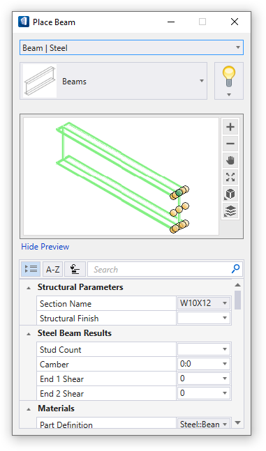
The Place Beam tool settings window opens so you can change placement settings, structural member data, and member coping settings.
Note: The default Catalog type is populated for the primary structural member, however you can select other catalog types to quickly place same type of beam elements. The combo box below it gets amended for the catalog items available for the selected type.This time your pointer remains as a crosshair because OpenBuildings Station Designer is waiting for you to identify where you want to place the first point of the girder. - For the first set of beams, we will use the a section size of W18X35. If that section size is not showing in your Section field, click the value field and use the section picker to find section W18X35.
-
The prompt in the status bar says Enter first point. Move your
pointer to the top of the column at the intersection of grid lines B and 1. You
will see the Structural Snaps target as you near the top of the column. Enter a
data point by pressing your left mouse button to place the first end point of
the beam.
Your pointer is still dynamically attached to the beam end, and the status bar prompts you to Enter end point.
-
Move your pointer across to the top of the column located at the
intersection of grid lines B and 2. You will see that column’s endpoint
Structural Snap target highlights. Click to place the end of the beam there.
Without resetting, place a second beam from B2 to B3. Because the beams are in
a continuous line, you can place them in sequence until the line must be
broken.
Tip: If you snap to the wrong location, and place the endpoint of the girder in the wrong place, you can correct your mistake. Click the Reset button (right mouse button) to abort placement, and then press <<Ctrl>+<z>> to undo your last action. The entire beam disappears, and now you should place the beam again, attached to the proper locations.
- At this point, OpenBuildings Station Designer believes you intend to continue placing members with the selected tool, and dynamically attaches another beam to your pointer. The status line still prompts you to Enter end point. We do not want to continue this line, so press your Reset button (the right mouse button) to discontinue placing any additional members of this type.
- We want to place another beam of the same size, but from the top of the short column at B4, in a straight line to the column at B3. Because the column at B3 is taller, we do not want to use the target at the top. Rather, we will let AccuDraw help us draw a straight beam. With the Place Steel Beam tool active, enter your first data point at the top of the column at B4. Move your mouse along the AccuDraw line towards the column. As you follow the AccuDraw path, the top line is highlighted thickly.
- When you see the thick highlight line, you know that you are moving along the AccuDraw guide. Press Enter to lock AccuDraw (you will see Enter SmartLock flash). Snap to the taller column to set the target for AccuDraw. Even though the snap target appears at the center of the column, AccuDraw will continue on the line.
- Enter a data point to accept the snap and place the beam.
- It will help us to see the section names in our view window. At the left bottom corner of the application window, you can select a different view group. Choose the Physical + Name group to display your section names.
- In the Place Steel Beam — Primary view control, change the section size to W16X26.
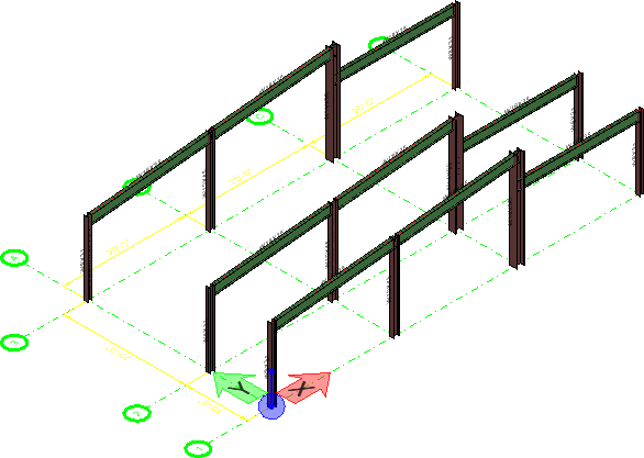
- Place beams from A1 — A2 and A2 — A3, just like the beams that we placed from B1 — B2 and B2 — B3. You can place these in sequence (without having to reset). Then, place beams from C1 — C2 and C2 — C3. Finally, place beams from A4 to A3 (parallel to the top of A4) and C4 to C3, just like the beam placed from B4 to B3. The result should look like the graphic shown below.
- Click Commit Changes to commit your changes to design history The Commit changes text box appears. Enter your changes and click OK.
-
Select the Show Design History tool.
The Design History dialog appears, displaying the list of comments you have created.